So it's been a few days since the end of the second summer session at NYU. Here is the documentation of all the projects past the doorbell!
No photo:
- I did get my feedback doorbell working, and I used an RGB led to change gradually from blue to red as the bell was 'woken' from its nap.
-The romance light sensor was the second lab assignment. We used an XBee in I/O mode to send a photocell reading over to a radio connected to an arduino. If the photocell reading was in the sweet spot for romance, it lit an led.
Our first major project was an implementation of a sensor (thermistor) network around the floor. My specific job was to build the circuits on breadboards so that they could be connected to power and have an xbee popped in and then forgotten about.
To read about this project in detail, check out Roy Vanegas's awesome documentation:
http://roy.vanegas.org/itp/sociable_objects_workshop/projects/itp_temperature_sensing_network/
The second project was an implementation of the sensor network, with the class split between sensor and actuator groups. The project that we decided on was a fountain that ran whenever someone in the bathroom flushed a toilet. We use capacitance/touch sensors on the toilet handles. I was part of the actuator group, and built a fountain using a small AC pump i bought from an aquarium store.
Somewhere down the line, we also had a one-day partnered assignment to respond to phrases with projects. Responding to "secrets", we modded the doorbell to connect a relay to turn on the audio chip from a hallmark card. The secret part? We detached the speaker and substituted an led to pulse according to the audio. We also built a headphone attachment with a phototransistor and an op amp that could pick up on the signal and turn the light back into sound. (It was the Harry Potter theme).
Here is the circuit with the LED and hallmark card part (the secret emitter)
Here is a close up the PCB that was actually inside the Hallmark card (with my LED attached). The two contacts where the wires are attached on the right were originally joined by a switch that was open when a paper strip was between two pieces of metal.
The secret reciever circuit(phototransistor > op amp > headphones)
And finally, I worked with two other people on a final project. The ideal vision was a pendulum that would release different colors of sand depending on activity in different rooms. The activity was to be detected by sound. We got pretty far, but not all the way. The sand-releasing contraption worked well (a servo rotated a disc with a hole in it to line up with one of three reservoirs of sand). The microphone, however, was not nearly sensitive enough (at least as we had it configured). We got it working well enough when you spoke/blew directly into it. Getting the sampling/averaging set up was a bit of work.
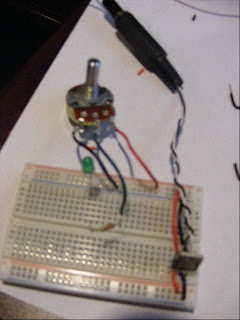
This is the microphone sensor circuit that we used in our final project.
Tuesday, August 11, 2009
Monday, July 6, 2009
Sociable Objects Workshop, Assignment 1: Doorbell
This blog is now my journal for Sociable Objects Workshop with Rob Faludi, the class I am taking the second session this summer.
The assignment was to make a doorbell with two Arduinos, two XBee radios, and a buzzer. The second and third parts of the assignment are to have a doorbell with feedback and a nap function. So far I have gotten to the doorbell with feedback, although I am having trouble making the feedback-LED work. Here is my simple doorbell (which works fine):
This is the actual doorbell unit, portable and powered by a 9 volt battery. It is running on an arduino mini. When the button is pressed and released, it sends the character 'r' out through the radio.
This is the buzzer part of the doorbell unit, powered by a desktop power supply. When the radio recieves the 'r' from the doorbell, the arduino turns on the DC buzzer for 1 second. It also prints the character 'w' for the purpose of feedback.
Although the code is there for the doorbell to light an LED when it recieves the 'w', it hasn't been working. When I write 'w' to the arduino serial directly, it works. I also noticed that one of the radios was working more reliably as the buzzer than the other, and I think the problem may be related to that.
Thursday, July 2, 2009
Monday, June 15, 2009
Motor/Transistor Labs
The first lab was to set up a motor running off it's own power with a TIP120 transistor. The potentiometer controls the motors speed by having the microcontroller pulse the transistor. The 9v battery is plugged into a 5v voltage regulator, which powers the motor. The arduino is powered by the USB.
The second lab involved setting up an H-bridge IC with the motor. The switch toggles between running the motor fowards and backwards.
Sunday, June 7, 2009
Serial Duplex
In this lab, multiple sensor values are sent to the computer via serial. A Processing sketch listens to the port and interperets the data, first separating the three sensor values, then reading the two analog values (potentiometers) as x and y coordinates for a circle and the one digital (button) value as whether or not to display the circle
(switching it from black to white)
The board:
The board and Processing sketch (note my hand pressing the button in the bottom left):
For my own interface, I sent serial data from a photoresistor reading to control the red and green values of a point light illuminating a sphere in Processing's 3d renderer:
(Note the position of my hand, blocking the photoresistor's light. As the photoresistor is put in darkness, the orange light on the blue sphere brightens.)
The board:
Serial Output
Thursday, June 4, 2009
Analog I/O Labs
Sorry about the delay putting these up, I had to wait to get a computer with an SD card reader. Luckily my laptop finally came back from the shop yesterday so I'll never have this problem again.
Analog input: The number of lights lit goes up as you bend the sensor. (I also did this with a photocell which was pretty cool, but I didnt take a picture)
Analog output (Servo Lab) : The servomotor/flex sensor combo is pretty weird; it's strange to have something move precisely with you as you push something else.
Monday, May 25, 2009
Lab 2: Digital I/O Using Arduino
The arduino powers one LED when the button is pressed, the other when it is not:
My combination lock interface: A coin operated lock (the 'unlocked' green LED goes on when all three coins are in)
Tinfoil circuit under the hood:
And finally, my dream device:
It is an interface for 3d modeling/digital sculpting. It would plug into the computer, and project a hologram (on top of the tinfoil) that the user (wearing the stylish leather interactive gloves) would be able to sculpt and shape with his hands instead of using a mouse/tablet.
Lab 1: Breadboard and introductory circuits
Thursday, May 21, 2009
Laptop...
Waiting for my beloved laptop to come back from the shop with a new motherboard. Until then, I don't have a computer with an SD card reader to put photos on here!
Subscribe to:
Posts (Atom)